- Lesson 1 Torque
- Lesson 2 Finding torque for angled forces
- Lesson 3 Rotational version of Newton's second law
- Lesson 4 More on moment of inertia
- Lesson 5 Rotational inertia
- Lesson 6 Rotational kinetic energy
- Lesson 7 Rolling without slipping problems
- Lesson 8 Constant angular momentum when no net torque
- Lesson 9 Angular momentum of an extended object
- Lesson 10 Ball hits rod angular momentum example
Torque
What is torque?
Torque is a measure of the force that can cause an object to rotate about an axis. Just as force is what causes an object to accelerate in linear kinematics, torque is what causes an object to acquire angular acceleration.
Torque is a vector quantity. The direction of the torque vector depends on the direction of the force on the axis.
Anyone who has ever opened a door has an intuitive understanding of torque. When a person opens a door, they push on the side of the door farthest from the hinges. Pushing on the side closest to the hinges requires considerably more force. Although the work done is the same in both cases (the larger force would be applied over a smaller distance) people generally prefer to apply less force, hence the usual location of the door handle.

Figure 1: Opening a door with maximum torque.
Torque can be either static or dynamic.
A static torque is one which does not produce an angular acceleration. Someone pushing on a closed door is applying a static torque to the door because the door is not rotating about its hinges, despite the force applied. Someone pedaling a bicycle at constant speed is also applying a static torque because they are not accelerating.
The drive shaft in a racing car accelerating from the start line is carrying a dynamic torque because it must be producing an angular acceleration of the wheels given that the car is accelerating along the track.
The terminology used when describing torque can be confusing. Engineers sometimes use the term moment, or moment of force interchangeably with torque. The radius at which the force acts is sometimes called the moment arm.
How is torque calculated?
The magnitude of the torque vector \[\tau\] for a torque produced by a given force \[F\] is
\[\tau = F \cdot r \sin(\theta)\]
where \[r\] is the length of the moment arm and \[\theta\] is the angle between the force vector and the moment arm. In the case of the door shown in Figure 1, the force is at right angles (90\[^\circ\]) to the moment arm, so the sine term becomes 1 and
\[\tau = F\cdot r\].
The direction of the torque vector is found by convention using the right hand grip rule. If a hand is curled around the axis of rotation with the fingers pointing in the direction of the force, then the torque vector points in the direction of the thumb as shown in Figure 2.
Explain: Isn't this somewhat arbitrary?


Figure 2: Direction of the torque vector found with the right-hand rule.
How is torque measured?
The SI unit for torque is the Newton-meter.
In imperial units, the Foot-pound is often used. This is confusing because colloquially the pound is sometimes used as a unit of mass and sometimes force. What is meant here is pound-force, the force due to earth gravity on a one-pound object. The magnitude of these units is often similar as \[1~\mathrm{Nm} \simeq 1.74~ \mathrm{ft}\cdot\mathrm{lbs}\].
Measuring a static torque in a non-rotating system is usually quite easy, and done by measuring a force. Given the length of the moment arm, the torque can be found directly. Measuring torque in a rotating system is considerably more difficult. One method works by measuring strain within the metal of a drive shaft which is transmitting torque and sending this information wirelessly.
What role does torque play in rotational kinematics?
In rotational kinematics, torque takes the place of force in linear kinematics. There is a direct equivalent to Newton’s 2ⁿᵈ law of motion (\[F=ma\]),
\[\tau = I \alpha\].
Here, \[\alpha\] is the angular acceleration. \[I\] is the rotational inertia, a property of a rotating system which depends on the mass distribution of the system. The larger \[I\], the harder it is for an object to acquire angular acceleration. We derive this expression in our article on rotational inertia.
What is rotational equilibrium?
The concept of rotational equilibrium is an equivalent to Newton’s 1ˢᵗ law for a rotational system. An object which is not rotating remains not rotating unless acted on by an external torque. Similarly, an object rotating at constant angular velocity remains rotating unless acted on by an external torque.
The concept of rotational equilibrium is particularly useful in problems involving multiple torques acting on a rotatable object. In this case it is the net torque which is important. If the net torque on a rotatable object is zero then it will be in rotational equilibrium and not able to acquire angular acceleration.
Exercise 1:
Consider the wheel shown in Figure 3, acted on by two forces. What magnitude of the force \[F_2\] will be required for the wheel to be in rotational equilibrium?

Figure 3: A wheel acted on by two torques.
How does torque relate to power and energy?
There is considerable confusion between torque, power and energy. For example, the torque of an engine is sometimes incorrectly described as its 'turning power'.
Torque and energy have the same dimensions (i.e. they can be written in the same fundamental units), but they are not a measure of the same thing. They differ in that torque is a vector quantity defined only for a rotatable system.
Power however, can be calculated from torque if the rotational speed is known. In fact, the horsepower of an engine is not typically measured directly, but calculated from measured torque and rotational speed. The relationship is:
\[\begin{aligned}
P &= \frac{\mathrm{Force} \cdot \mathrm{Distance}}{\mathrm{Time}} \\
& = \frac{\mathrm{F} \cdot 2\pi r}{t} \\
&= 2\pi \tau \omega \qquad \mathrm{(\omega~in~ revolutions/sec)} \\
&= \tau \omega \qquad \mathrm{(\omega~in~radian/sec)}\end{aligned}\]
Along with horsepower, the peak torque produced by a vehicle engine is an important and commonly quoted specification. Practically speaking, peak torque is relevant for generally describing how quickly a vehicle will accelerate and its ability to pull a load. Horsepower (relative to weight) on the other hand is more relevant to the maximum speed of a vehicle.
Explain
It is important to recognize that while maximum torque and horsepower are useful general specifications, they are of limited use when making calculations involving the overall motion of a vehicle. This is because in practice both vary as a function of rotational speed. The general relationship can be non-linear and differs for different types of motor as shown in Figure 4.
Explain

Figure 4: Relationship of available torque to rotational speed for different sources.
How can we increase or decrease torque?
It is often necessary to increase or decrease the torque produced by a motor to suit different applications. Recall that the length of a lever can increase or decrease the force on an object at the expense of the distance through which the lever must be pushed. Similarly, the torque produced by a motor can be increased or decreased through the use of gearing. An increase in torque comes with a proportional decrease in rotational speed. The meshing of two gear teeth can be viewed as equivalent to the interaction of a pair of levers as shown in Figure 5.

Figure 5: The meshing of two gears viewed as the interaction of two levers.
The use of adjustable gearing is necessary to obtain good performance in vehicles powered by combustion engines. These engines produce maximum torque only for a narrow range of high rotational speeds. Adjustable gearing allows sufficient torque to be delivered to the wheels at any given rotational speed of the engine.
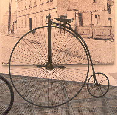
Bicycles require gearing because of the inability of humans to pedal with a cadence sufficient to achieve a useful speed when driving a wheel directly (unless one is cycling a penny-farthing).
Explain
Adjustable gearing is not typically required in vehicles powered by steam engines or electric motors. In both cases, high torque is available at low speeds and is relatively constant over a wide range of speeds.
Exercise 2a:
A gasoline engine producing \[150~\mathrm{Nm}\] of torque at a rotational speed of \[300~\mathrm{rad/s}\] is used to drive a winch and lift a weight as shown in figure 6. The winch drum has a radius of 0.25 m and is driven from the engine via a 1:50 speed reduction gear. What mass could be raised with this setup? (Assume the winch is in rotational equilibrium, i.e. the mass is traveling up at constant velocity).

Figure 6: Engine-driven winch used to lift a mass (exercise 2).
Exercise 2b:
At what speed would the weight be traveling upward?
Data sources
Cyclist : Hansen, E.A, Smith G. Factors affecting cadence choice during submaximal cycling and cadence influence on performance. International Journal of Sports Physiology and Performance. March 2009; 4(1):3-17.
Diesel engine: Mercedes 250 CDI
Otto cycle engine: Mercedes E250
Electric motor: Tesla Model S 85
Steam locomotive: 2-8-0 "Consolidation" Locomotive at 70% boiler capacity
Finding torque for angled forces
Rotational version of Newton's second law
More on moment of inertia
Rotational inertia
What is rotational inertia?
Rotational inertia is a property of any object which can be rotated. It is a scalar value which tells us how difficult it is to change the rotational velocity of the object around a given rotational axis.
Rotational inertia plays a similar role in rotational mechanics to mass in linear mechanics. Indeed, the rotational inertia of an object depends on its mass. It also depends on the distribution of that mass relative to the axis of rotation.
When a mass moves further from the axis of rotation it becomes increasingly more difficult to change the rotational velocity of the system. Intuitively, this is because the mass is now carrying more momentum with it around the circle (due to the higher speed) and because the momentum vector is changing more quickly. Both of these effects depend on the distance from the axis.
Rotational inertia is given the symbol \[I\]. For a single body such as the tennis ball of mass \[m\] (shown in Figure 1), rotating at radius \[r\] from the axis of rotation the rotational inertia is
\[I = mr^2\]
and consequently rotational inertia has SI units of \[\mathrm{kg\cdot m^2}\].
Rotational inertia is also commonly known as moment of inertia. It is also sometimes called the second moment of mass; the 'second' here refers to the fact that it depends on the length of the moment arm squared.

Figure 1: A tethered tennis ball rotating about a central point.
How does rotational inertia relate to Newton's 2ⁿᵈ law?
Rotational inertia takes the place of mass in the rotational version of Newton's 2ⁿᵈ law.
Consider a mass \[m\] attached to one end of a massless rod. The other end of the rod is hinged so that the system can rotate about the central hinge point as shown in Figure 2.

Figure 2: A mass rotating due to a tangential force.
We now start rotating the system by applying a tangential force \[F_T\] to the mass. From Newton’s 2ⁿᵈ law,
\[F_T = m a_T\].
this can also be written as
\[F_T = m (r \alpha)\].
Newton's 2ⁿᵈ law relates force to acceleration. In rotational mechanics torque \[\tau\] takes the place of force. Multiplying both sides by the radius gives the expression we want.
\[\begin{aligned} F_T r &= m (r \alpha) r\\ \tau &= m r^2 \alpha \\ \tau &= I \alpha\end{aligned}\]
This expression can now be used to find the behavior of a mass in response to a known torque.
Exercise 1a:
A motor capable of producing a constant torque of \[100~\mathrm{Nm}\] and a maximum rotation speed of \[150~\mathrm{rad/s}\] is connected to a flywheel with rotational inertia \[0.1~\mathrm{kg m^2}\]. What angular acceleration will the flywheel experience as the motor is switched on?
Solution
Exercise 1b:
How long will the flywheel take to reach a steady speed if starting from rest?
Solution
How can we calculate rotational inertia in general?
Often mechanical systems are made of many masses connected together, or complex shapes.
It is possible to calculate the total rotational inertia for any shape about any axis by summing the rotational inertia of each mass.
\[\begin{aligned} I &= m_1 r_1^2 + m_2 r_2^2 + \ldots \\ &= \Sigma m_i r_i^2 \end{aligned}\]

Figure 3: A rigid system of masses shown with two different rotation axes.
Exercise 2a:
Consider the object shown in figure 3(a). What is its rotational inertia?
Solution
Exercise 2b:
Consider the alternate case of Figure 3(b) of the same system rotating about a different axis. What would you expect the rotational inertia to be in this case?
Solution
How can we find the rotational inertia of complex shapes?
For more complicated shapes, it is generally necessary to use calculus to find the rotational inertia. However, for many common geometric shapes it is possible to find tables of equations for the rotational inertia in textbooks or other sources. These typically give the moment of inertia for a shape rotated about its centroid (which often corresponds with the shapes center of mass).
For example, the rotational inertia of a solid cylinder with radius \[r\] rotated about a central axis is
\[I = \frac{1}{2}m r^2\]
and for a hollow cylinder with inner and outer radii \[r_i\] and \[r_o\] respectively,
\[I = \frac{m(r_i^2 + r_o^2)}{2}\]
Expressions for other simple shapes are shown in Figure 4.
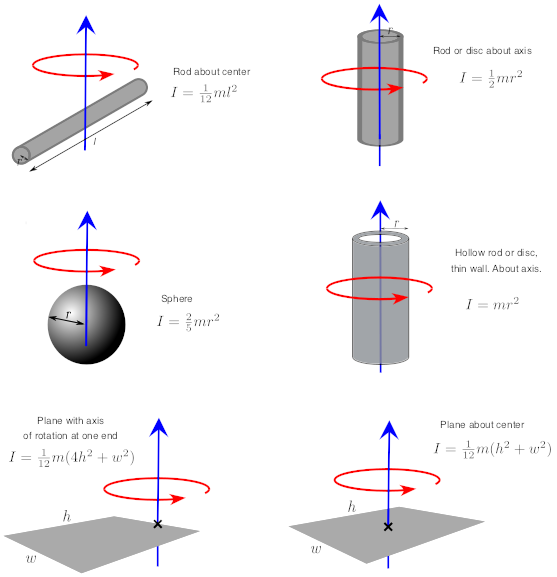
Figure 4: Equations for the rotational inertia of some simple shapes under rotation.
Complex shapes can often be represented as combinations of simple shapes for which there exists a known equation for rotational inertia. We can then combine these rotational inertia to find that of the composite object.
The problem that we will likely run into when combining simple shapes is that the equations tell us the rotational inertia as found about the centroid of the shape and this does not necessarily correspond to the axis of rotation of our composite shape. We can account for this using the parallel axis theorem.
The parallel axis theorem allows us to find the moment of inertia of an object about a point \[o\] as long as we known the moment of inertia of the shape around its centroid \[c\], mass \[m\] and distance \[d\] between points \[o\] and \[c\].
\[\boxed{I_o = I_c + md^2}\]
Exercise 3:
If the shape shown in Figure 5 is made by welding three \[10~\mathrm{mm}\] thick metal discs (each with mass \[50~\mathrm{kg}\]) to a metal ring with mass \[100~\mathrm{kg}\]. If rotated about a central axis (out of the page), what is the rotational inertia of the object?
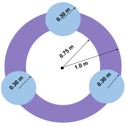
Figure 5: A system of one large hollow disc and three smaller filled discs.
Where else does rotational inertia come up in physics?
Rotational inertia is important in almost all physics problems that involve mass in rotational motion. It is used to calculate angular momentum and allows us to explain (via conservation of angular momentum) how rotational motion changes when the distribution of mass changes. It also is needed to find the energy which is stored as rotational kinetic energy in a spinning flywheel.